Most of KBR’s multimess devices of the F96 and F144 versions have the ‘Extreme value’ function. So does multicount. With this function, the maximum and minimum values of the most important measuring parameters are saved in the device with the time of occurrence. As of device version 4.5 R3, the bus master can periodically read these extreme values and reset them in the measuring device.
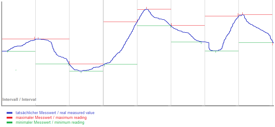
The interval is identical to the capture interval of the corresponding medium (in this case electricity). However, the timestamp is that of the extreme values. visual energy 4 can retrieve the extreme values using the EDIFACT service.
Setup acquisition extreme values
- Log in the configuration website of the Busmaster.
- In the settings of a Location in ‘Automation’ you can activate the ‘Extreme value recording’. These setting will be take on for all connected Bus segments. In the settings of a Bus segment, the option can be deactivated, e.g. when no extreme value recording is necessary at this measured point.
Check extreme value recording at the Busmaster
In the respective Bus segment in the Automation tab you can see the extreme value automation
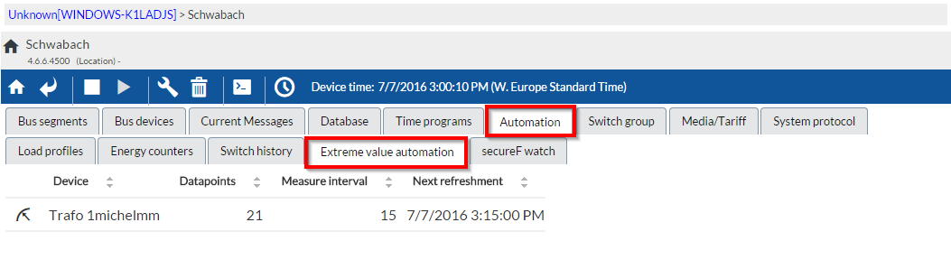
In addition to the device address and device name, the automation tab also shows the number of detected data points, the measurement interval and the time of the next reading. Click on a device data set to switch to the device view…
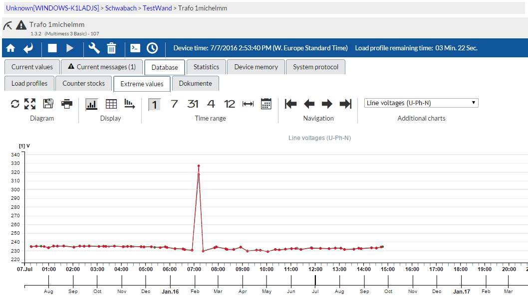
List of extreme values
| Value | OBIS Code | Description |
|---|---|---|
| Max: U L1-N | 1-0:32.6.0*0 | Max. voltage between phase L1 and neutral conductor |
| Max: U L2-N | 1-0:52.6.0*0 | Max. voltage between phase L2 and neutral conductor |
| Max: U L3-N | 1-0:72.6.0*0 | Max. voltage between phase L3 and neutral conductor |
| Min: U L1-N | 1-0:32.3.0*0 | Min. voltage between phase L1 and neutral conductor |
| Min: U L2-N | 1-0:52.3.0*0 | Min. voltage between phase L2 and neutral conductor |
| Min: U L3-N | 1-0:72.3.0*0 | Min. voltage between phase L3 and neutral conductor |
| Max: U L1-L2 | 1-0:81.6.10*0 | Max. voltage between phases L1 and L2 |
| Max: U L2-L3 | 1-0:81.6.21*0 | Max. voltage between phases L2 and L3 |
| Max: U L3-L1 | 1-0:81.6.2*0 | Max. voltage between phases L3 and L1 |
| Min: U L1-L2 | 1-0:81.3.10*0 | Min. voltage between phases L1 and L2 |
| Min: U L2-L3 | 1-0:81.3.21*0 | Min. voltage between phases L2 and L3 |
| Min: U L3-L1 | 1-0:81.3.2*0 | Min. voltage between phases L3 and L1 |
| Max: Is L1 | 1-0:31.6.0*0 | Max. apparent current L1 |
| Max: Is L2 | 1-0:51.6.0*0 | Max. apparent current L2 |
| Max: Is L3 | 1-0:71.6.0*0 | Max. apparent current L3 |
| Max: IAvg L1 | 1-0:31.6.0*1 | Max. average apparent current L1 |
| Max: IAvg L2 | 1-0:51.6.0*1 | Max. average apparent current L2 |
| Max: IAvg L3 | 1-0:71.6.0*1 | Max. average apparent current L3 |
| Max: IN | 1-0:91.6.0*0 | Max. neutral conductor apparent current |
| Max: IN Avg | 1-0:91.6.0*1 | Max. average neutral conductor apparent current |
| Max: Thd U L1 | Max. voltage distortion factor (%) L1 | |
| Max: Thd U L2 | Max. voltage distortion factor (%) L2 | |
| Max: Thd U L3 | Max. voltage distortion factor (%) L3 |
Configure further extreme values
The configuration file ExtremeValueIndex.xml is saved in the “ExtremeValues” subdirectory of the eBus master service directory (default: “D:\KBR\Data\Kbr.EbusMaster.CommunicationService\2.0.0.0”). With this file, you can define the extreme values to be read.
<?xml version="1.0" encoding="utf-8" ?>
<extremevalues version="4.5.3000">
<deviceclass classguid="c84e4b3d-ef55-4cda-ae2c-83fbb3fce59f" name="multimess 3F144-1-LED">
<version value="4.5.3" firstversion="0.0.0" lastversion="0.0.0" >mmess_3_4_base.xml</version>
</deviceclass>
</extremevalues>
You need one <deviceclass> node per device type. As a minimum, it must be assigned the “classguid” attribute by defining a unique device class GUID in the eBus master. This combination may only be included once within the <extremevalues> root node.
As the extreme value data points might vary depending on the version, a <version> node is included. It contains 3 attributes:
- value = the version designation
- firstversion = the first device firmware version for which the setting applies
- lastversion = the last device firmware version for which the setting applies
The version information “0.0.0” indicates “undefined”, meaning that there are no limitations in terms of the first or last version.
In the <version> node value, the XML file name defining the extreme values of this device version is specified.
The corresponding file has to be in the same directory and is structured as follows:
<?xml version="1.0" encoding="utf-8" ?>
<deviceclass>
<extremevalue id="UPhN.Max.L1" default="true" obiscode="1-0:32.6.0*0" name="U PH-N L1 MAX" value="ExtremeValues.UPhN.Max.L1.Value" timestamp="ExtremeValues.UPhN.Max.L1.TimeStamp" reset="ExtremeValues.UPhN.Max.L1.Reset">
  </extremevalue>

...
<extremevaluegroup default="false" reset="ExtremeValues.Thd.U.ResetAllMax" name="U Thd" id="U.Thd">
...
 <extremevalue id="Thd.U.Thd.Max.L1" obiscode="1-0:32.6.124*0" name="Thd U L1 MAX" value="ExtremeValues.Thd.U.Thd.Max.L1.Value" timestamp="ExtremeValues.Thd.U.Thd.Max.L1.TimeStamp">

</extremevalue>

<extremevalue id="Thd.U.Thd.Max.L2" obiscode="1-0:52.6.124*0" name="Thd U L2 MAX" value="ExtremeValues.Thd.U.Thd.Max.L2.Value" timestamp="ExtremeValues.Thd.U.Thd.Max.L2.TimeStamp">

</extremevalue>

</extremevaluegroup>

</deviceclass>
The XML file begins with the <deviceclass> root node, which can have two types of subnodes: <extremevalue> and <extremevaluegroup>
- <extremevalue> defines an individual extreme value with the following attributes: • id : Item ID designation of the extreme value data point • obiscode: OBIS code of the extreme value • name: legible designation of the extreme value • value: Item ID of the data point that includes the extreme value • timestamp: Item ID of the data point that includes the timestamp of the extreme value • reset: Item ID of the data point that includes the reset command of the extreme value.<extremevaluegroup> defines a group of extreme values that share a common reset command. In this group, you can find the corresponding <extremevalue> nodes. The reset attribute, however, is located in the group node.
- <extremevaluegroup> definiert eine Gruppe von Extremwerten, die einen gemeinsamen Reset-Befehl besitzen. Darunter sind wieder die entsprechenden <extremevalue>-Knoten. Das reset-Attribut sitzt allerdings im Gruppenknoten.
For certain individual devices, you can make special extreme value settings. For this purpose, the ‘ExtremeValueIndex.xml’ file has to include one <device> node per device with the “id” attribute, to which a unique device GUID is assigned.The node The Again, the node value has the name of the XML file that contains the settings (as described above).